Task And Function part 2
Thursday, 09 September 2021 13:31
Semicon Editor 01
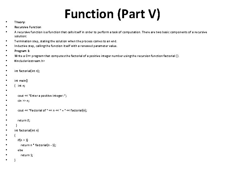
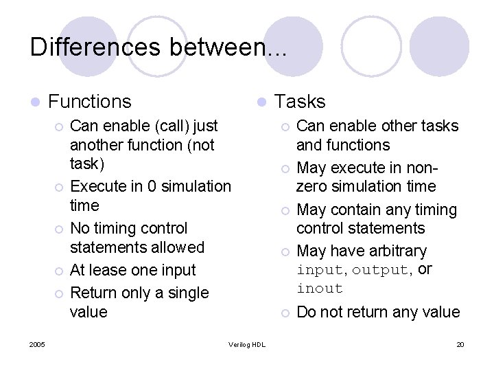 Function A Verilog HDL function is the same as a task, with very little differences, like function cannot drive more than one output, can not contain delays.
Last Updated ( Tuesday, 29 March 2022 00:58 )
Read more...
Task And Function part 1
Tuesday, 07 September 2021 13:51
Semicon Editor 01
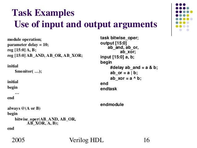
 Task Tasks are used in all programming languages, generally known as procedures or subroutines. The lines of code are enclosed in task....end task brackets.
Last Updated ( Tuesday, 29 March 2022 00:58 )
Read more...
Verilog Operators Part-II
Tuesday, 07 September 2021 13:43
Semicon Editor 01
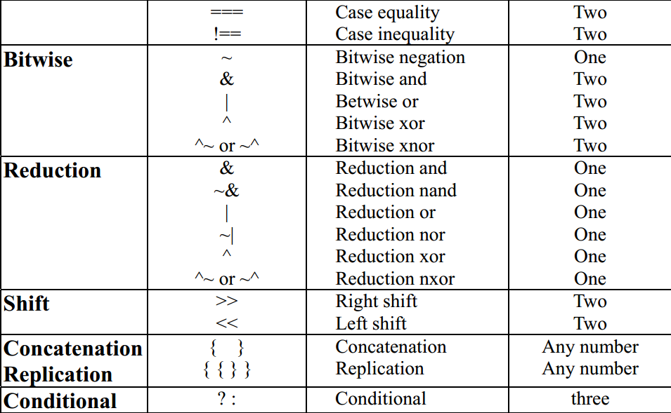 Reduction Operators
Last Updated ( Tuesday, 29 March 2022 00:59 )
Read more...
Verilog Operators Part 1
Tuesday, 07 September 2021 13:30
Semicon Editor 01
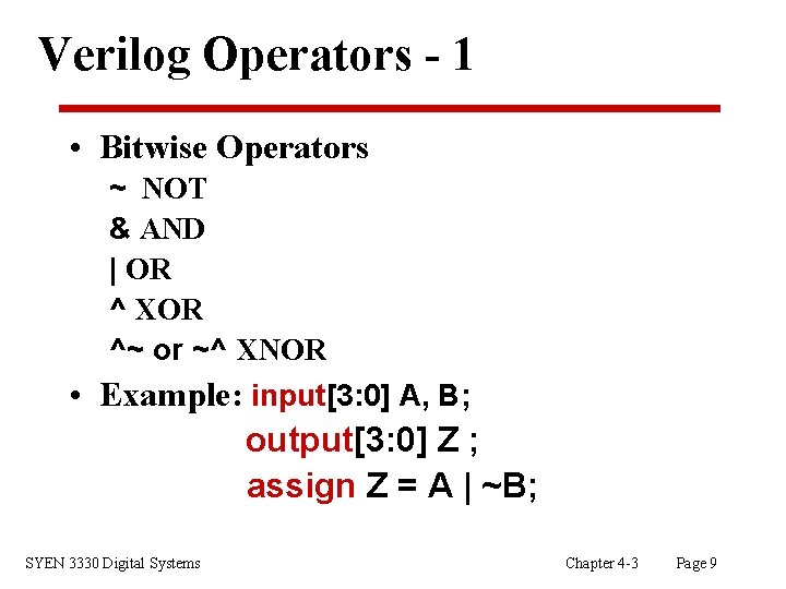 Arithmetic Operators Binary: +, -, *, /, % (the modulus operator) Unary: +, - (This is used to specify the sign)
Last Updated ( Tuesday, 29 March 2022 00:59 )
Read more...
User Defined Primitives Part-III
Saturday, 04 September 2021 13:35
Semicon Editor 01
 Level Sensitive Sequential UDP
Level-sensitive sequential behavior is represented in the same way as combinational behavior, except that the output is declared to be of type reg, and there is an additional field in each table entry. This new field represents the current state of the UDP.
Last Updated ( Tuesday, 29 March 2022 00:59 )
Read more...
User Defined Primitives Part-II
Saturday, 04 September 2021 13:21
Semicon Editor 01
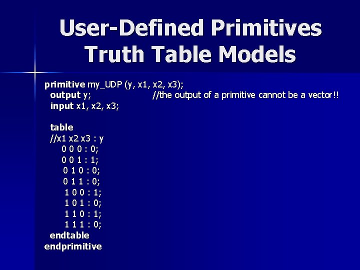
 Combinational UDPs In combinational UDPs, the output is determined as a function of the current input. Whenever an input changes value, the UDP is evaluated and one of the state table rows is matched.
Last Updated ( Tuesday, 29 March 2022 00:59 )
Read more...
User Defined Primitives Part-I
Saturday, 04 September 2021 13:05
Semicon Editor 01
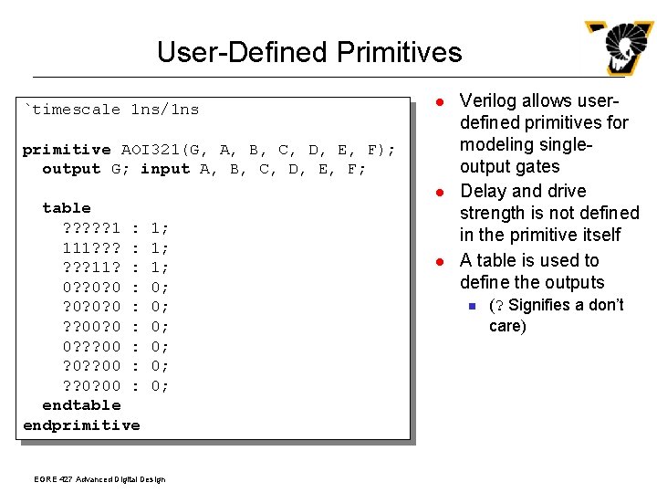 Introduction Verilog has built-in primitives like gates, transmission gates, and switches. This is a rather small number of primitives; if we need more complex primitives, then Verilog provides UDP,
Last Updated ( Tuesday, 29 March 2022 00:59 )
Read more...
My first program in Verilog
Tuesday, 31 August 2021 15:23
Semicon Editor 01
 Introduction If you refer to any book on programming languages, it starts with an "Hello World" program; once you have written it, you can be sure that you can do something in that language
Last Updated ( Tuesday, 31 August 2021 15:34 )
Read more...
Art of Writing TestBenches Part - II
Tuesday, 31 August 2021 15:16
Semicon Editor 01
 Writing a TestBench First step of any testbench creation is building a dummy template which basically declares inputs to DUT as reg and outputs from DUT as wire, then instantiates the DUT as shown in the code below.
Last Updated ( Tuesday, 29 March 2022 01:00 )
Read more...
Art of Writing TestBenches Part - I
Tuesday, 31 August 2021 15:02
Semicon Editor 01
Introduction
Writing a testbench is as complex as writing the RTL code itself. These days ASICs are getting more and more complex and thus verifying these complex ASIC has become a challenge. Typically 60-70% of time needed for any ASIC is spent on verification/validation/testing.
Last Updated ( Tuesday, 29 March 2022 01:00 )
Read more...
System Task and Function
Sunday, 29 August 2021 14:06
Semicon Editor 01
 Introduction There are tasks and functions that are used to generate input and output during simulation. Their names begin with a dollar sign ($). The synthesis tools parse and ignore system functions, and hence can be included even in synthesizable models.
Last Updated ( Sunday, 29 August 2021 14:12 )
Read more...
Compiler Directives
Sunday, 29 August 2021 13:56
Semicon Editor 01
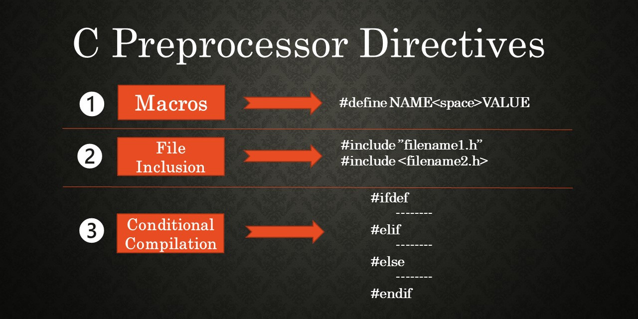 Introduction A compiler directive may be used to control the compilation of a Verilog description. The grave accent mark, `, denotes a compiler directive.
Last Updated ( Sunday, 29 August 2021 14:01 )
Read more...
Modeling Memories And FSM Part - II
Sunday, 29 August 2021 13:43
Semicon Editor 01
 Introduction to FSM State machines or FSM are the heart of any digital design; of course a counter is a simple form of FSM. When I was learning Verilog, I used to wonder "How do I code FSM in Verilog" | and "What is the best way to code it". I will try to answer the first part of the question below and second part of the question can be found in the tidbits section. State machine Types There are two types of state machines as classified by the types of outputs generated from each. The first is the Moore State Machine where the outputs are only a function of the present state, the second is the Mealy State Machine where one or more of the outputs are a function of the present state and one or more of the inputs. Moore Model 
State machines can also be classified according to the state encoding used. Encoding style is also a critical factor which decides speed and gate complexity of the FSM. Binary, gray, one hot, one cold, and almost one hot are the different types of encoding styles used in coding FSM states. Modeling State machines. One thing that need to be kept in mind when coding FSM is that combinational logic and sequence logic should be in two different always blocks. In the above two figures, next state logic is always the combinational logic. State Registers and Output logic are sequential logic. It is very important that any asynchronous signal to the next state logic be synchronized before being fed to the FSM. Always try to keep FSM in a separate Verilog file.
Using constants declaration like parameter or `define to define states of the FSM makes code more readable and easy to manage. We will be using the arbiter FSM to study FSM coding styles in Verilog Verilog Code | FSM code should have three sections: | - Encoding style.
- Combinational part.
- Sequential part.
There are many encoding styles around, some of which are: - Binary Encoding
- One Hot Encoding
- One Cold Encoding
- Almost One Hot Encoding
- Almost One Cold Encoding
- Gray Encoding
Of all the above types we normally use one hot and binary encoding. | One Hot Encoding | | 1 parameter [4:0] IDLE = 5'b0_0001; 2 parameter [4:0] GNT0 = 5'b0_0010; 3 parameter [4:0] GNT1 = 5'b0_0100; 4 parameter [4:0] GNT2 = 5'b0_1000; 5 parameter [4:0] GNT3 = 5'b1_0000; | | Binary Encoding | | 1 parameter [2:0] IDLE = 3'b000; 2 parameter [2:0] GNT0 = 3'b001; 3 parameter [2:0] GNT1 = 3'b010; 4 parameter [2:0] GNT2 = 3'b011; 5 parameter [2:0] GNT3 = 3'b100; | | Gray Encoding | | 1 parameter [2:0] IDLE = 3'b000; 2 parameter [2:0] GNT0 = 3'b001; 3 parameter [2:0] GNT1 = 3'b011; 4 parameter [2:0] GNT2 = 3'b010; 5 parameter [2:0] GNT3 = 3'b110; | Bạn Có Đam Mê Với Vi Mạch hay Nhúng - Bạn Muốn Trau Dồi Thêm Kĩ Năng Mong Muốn Có Thêm Cơ Hội Trong Công Việc Và Trở Thành Một Người Có Giá Trị Hơn Bạn Chưa Biết Phương Thức Nào Nhanh Chóng Để Đạt Được ChúngHãy Để Chúng Tôi Hỗ Trợ Cho Bạn. SEMICON 
Last Updated ( Tuesday, 29 March 2022 01:00 )
Modeling Memories And FSM Part - I
Saturday, 28 August 2021 15:00
Semicon Editor 01
 Memory Modeling To help modeling of memory, Verilog provides support for two dimensions arrays. Behavioral models of memories are modeled by declaring an array of register variables; any word in the array may be accessed using an index into the array. A temporary variable is required to access a discrete bit within the array.
Last Updated ( Tuesday, 29 March 2022 01:00 )
Read more...
Verilog Quick Reference part 2
Saturday, 28 August 2021 14:51
Semicon Editor 01
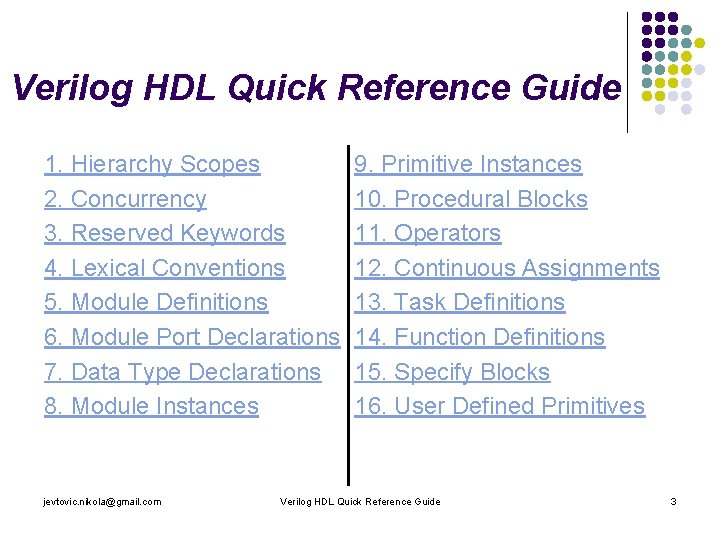 SYSTEM TASKSbut mentioned in the informative appendix. INPUT
Last Updated ( Tuesday, 29 March 2022 01:01 )
Read more...
|
|