PCMCIA 32 bit Interface Bus
Sunday, 27 June 2010 16:33
administrator

PCMCIA Defines both the Electrical and Physical specifications for a 68 pin interface residing in one of 3 form factors, which differ only in thickness; Type I: 3.3mm x 85.6mm x 54.0mm (TxLxW), Version 2.1 allows the length to increase 50mm to 135mm
Type II: 5.0mm x 85.6mm x 54.0mm (TxLxW), Version 2.1 allows the length to increase 50mm to 135mm
Type III: 10.5mm x 85.6mm x 54.0mm (TxLxW)
Last Updated ( Friday, 31 May 2013 15:59 )
Read more...
IDE (ATA) Interface Bus
Sunday, 27 June 2010 16:29
administrator

IDE / ATA Parallel Bus Description Nominally called the IDE (Integrated Drive Electronics) bus; how ever it's more correctly known as the ATA (Advanced Technology Attachment) specification [ATA Bus].
Last Updated ( Friday, 31 May 2013 16:00 )
Read more...
Serial ATA (SATA) Interface Bus
Sunday, 27 June 2010 16:26
administrator

Serial ATA Description The Serial ATA bus [SATA] is the serial version of the IDE [ATA] spec. SATA uses a 4 conductor cable with two differential pairs [Tx/Rx], plus an additional three grounds pins and a separate power connector. Data runs at 150MBps [1.5GHz] using 8B/10B encoding and 250mV signal swings, with a maximum bus length of 1 meter.
Last Updated ( Friday, 31 May 2013 16:03 )
Read more...
Gigabit Ethernet Interface Bus
Sunday, 27 June 2010 14:28
administrator

Gigabit Ethernet Description The Ethernet standard uses Manchester Encoding and Decoding. Access control is gained via Carrier Sense, Multiple Access with Collision Detect (CSMA_CD). However 10 Gigabit Ethernet [10GE] only uses Full-duplex, so CSMA/CD is not required. Preamble Field:
Last Updated ( Friday, 19 November 2010 12:09 )
Read more...
PCI Express Interface Bus
Sunday, 27 June 2010 14:20
administrator

PCI Express Bus Description A description of the new Serial PCI Bus "PCI Express".
The PCI Express [PCIe] bus defines the Electrical, topology and protocol for the physical layer of a point to point serial interface over copper wire or optical fiber.
Last Updated ( Friday, 19 November 2010 12:11 )
Read more...
I2S Interface Bus
Sunday, 27 June 2010 14:19
administrator

Inter-IC Sound Description I2S Bus (IIS, or I2S) is a serial bus designed for digital audio devices. The I2S design handles audio data separately from clock signals. An I2S bus design consists of three serial bus lines: a line with two time-division multiplexing (TDM) data channels [SD], a word select line [WS], and a clock line [SCK].
Last Updated ( Friday, 19 November 2010 12:12 )
Read more...
SCI Interface Bus
Sunday, 27 June 2010 14:12
administrator

SCI [Serial Communications Interface] is an asynchronous serial communications bus used between uP [CPUs] and peripheral devices [EPROMs for example]. Two signal lines are used with SCI: TXD [Transmit], and RXD [Receive].
The two wire SCI bus operates in Full-duplex mode [transmitting and receiving at the same time.
Last Updated ( Friday, 19 November 2010 12:14 )
Read more...
JTAG Interface Bus
Sunday, 27 June 2010 14:09
administrator
 IEEE Std 1149.1-1990 JTAG (Joint Test Action Group); Test Access Port and Boundary-Scan Architecture. This is a serial bus with four signals: Test Clock (TCK), Test Mode Select (TMS), Test Data Input (TDI), and Test Data Output (TDO). The bus is used as a test bus for the 'Boundary-Scan' of ICs, as in Design-For-Testability (DFT). To use JTAG, during the design, you most select JTAG compatible devices. ICs supporting JTAG will have the four additional pins listed above.
Last Updated ( Friday, 19 November 2010 12:16 )
Read more...
I2C Interface Bus
Sunday, 27 June 2010 14:07
administrator
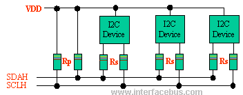 I2C Bus Description I2C bus was developed by Philips Semiconductors [NXP], originally designed to be a battery control interface.
The I2C interface standard defines both the electrical layer and protocol layer.
The I2C bus uses a bi-directional Serial Clock Line [SCL] and Serial Data Lines [SDA]. Both the SCL and SDA lines are pulled high via an Rp resistor.
Last Updated ( Monday, 23 September 2013 13:57 )
Read more...
PCI Express là gì?
Sunday, 27 June 2010 13:49
administrator
![[Image: maychu2.jpg]](http://www.echip.com.vn/echiproot/images/2004/so82/maychu2.jpg)
Cách đây 8 năm, khi ra đời vào năm 1996, giao diện AGP (Ac celerated Graphics Port, cổng đồ họa tăng tốc), đã nổi đình nổi đám vì giải phóng được băng thông xử lý tín hiệu đồ họa vốn bó rị ở 133MB/s của bus PCI. Tốc độ AGP 1X có băng thông 266MB/s và AGP 8X (hay AGP 3.0 theo đặc tả của Intel) hiện nay đạt 2,1GB/s.
Last Updated ( Tuesday, 20 July 2010 16:59 )
Read more...
Vi mạch khuyếch đại thuật toán 741
Saturday, 26 June 2010 23:19
administrator
 Vi mạch khuyếch đại thuật toán 741 có hai đầu vào + "INVERTING ( - )":Đảo + "NON-INVERTING (+)": Thuận và đầu ra ở chân 6.
Last Updated ( Friday, 31 May 2013 16:22 )
Read more...
Mô tả nghi thức HDLC (HDLC protocol)
Friday, 25 June 2010 11:27
administrator

HDLC [High-level Data Link Control] is a group of protocols for transmitting [synchronous] data [Packets] between [Point-to-Point] nodes. In HDLC, data is organized into a frame. HDLC protocol resides with Layer 2 of the OSI model, the data link layer. HDLC uses zero insertion/deletion process [bit stuffing] to ensure that the bit pattern of the delimiter flag does not occur in the fields between flags. The HDLC frame is synchronous and therefore relies on the physical layer to provide method of clocking and synchronizing the transmission and reception of frames.
Last Updated ( Monday, 23 September 2013 14:05 )
Read more...
ASIC Design Flow
Thursday, 24 June 2010 21:55
administrator
Introduction Being new to Verilog you might want to try some examples and try designing something new. I have listed the tool flow that could be used to achieve this. I have personally tried this flow and found this to be working just fine for me.
Last Updated ( Friday, 29 November 2013 14:08 )
Read more...
Học Verilog trong 1 ngày (phần IV)
Thursday, 24 June 2010 21:49
administrator
Last Updated ( Saturday, 01 June 2013 15:22 )
Read more...
Học Verilog trong 1 ngày (phần III)
Thursday, 24 June 2010 21:40
administrator
Last Updated ( Saturday, 01 June 2013 15:22 )
Read more...
|
|