


Modules
| Ports |
- Ports allow communication between a module and its environment.
- All but the top-level modules in a hierarchy have ports.
- Ports can be associated by order or by name.
You declare ports to be input, output or inout. The port declaration syntax is :
| input [range_val:range_var] list_of_identifiers; |
| output [range_val:range_var] list_of_identifiers; |
| inout [range_val:range_var] list_of_identifiers; |
| NOTE : As a good coding practice, there should be only one port identifier per line, as shown below |
| Examples : Port Declaration |
| 1 input clk ; // clock input 2 input [15:0] data_in ; // 16 bit data input bus 3 output [7:0] count ; // 8 bit counter output 4 inout data_bi ; // Bi-Directional data bus |
Examples : A complete Example in Verilog
1 module addbit (
2 a , // first input
3 b , // Second input
4 ci , // Carry input
5 sum , // sum output
6 co // carry output
7 );
8 //Input declaration
9 input a;
10 input b;
11 input ci;
12 //Ouput declaration
13 output sum;
14 output co;
15 //Port Data types
16 wire a;
17 wire b;
18 wire ci;
19 wire sum;
20 wire co;
21 //Code starts here
22 assign {co,sum} = a + b + ci;
23
24 endmodule // End of Module addbit
Modules connected by port order (implicit)
Here order should match correctly. Normally it's not a good idea to connect ports implicitly. It could cause problem in debug (for example: locating the port which is causing a compile error), when any port is added or deleted.
1 //-----------------------------------------------------
2 // This is simple adder Program
3 // Design Name : adder_implicit
4 // File Name : adder_implicit.v
5 // Function : This program shows how implicit
6 // port connection are done
7 // Coder : Deepak Kumar Tala
8 //-----------------------------------------------------
9 module adder_implicit (
10 result , // Output of the adder
11 carry , // Carry output of adder
12 r1 , // first input
13 r2 , // second input
14 ci // carry input
15 ); 16 17 // Input Port Declarations
18 input [3:0] r1 ;
19 input [3:0] r2 ;
20 input ci ;
21 22 // Output Port Declarations
23 output [3:0] result ;
24 output carry ;
25 26 // Port Wires
27 wire [3:0] r1 ;
28 wire [3:0] r2 ;
29 wire ci ;
30 wire [3:0] result ;
31 wire carry ;
32 33 // Internal variables
34 wire c1 ;
35 wire c2 ;
36 wire c3 ;
37 38 // Code Starts Here
39 addbit u0 ( 40 r1[0] , 41 r2[0] , 42 ci , 43 result[0] , 44 c1 45 ); 46 47 addbit u1 ( 48 r1[1] , 49 r2[1] , 50 c1 , 51 result[1] , 52 c2 53 ); 54 55 addbit u2 ( 56 r1[2] , 57 r2[2] , 58 c2 , 59 result[2] , 60 c3 61 ); 62 63 addbit u3 ( 64 r1[3] , 65 r2[3] , 66 c3 , 67 result[3] , 68 carry 69 ); 70 71 endmodule // End Of Module adder
Modules connected by name
Here the name should match with the leaf module, the order is not important.
1 //-----------------------------------------------------
2 // This is simple adder Program
3 // Design Name : adder_explicit
4 // File Name : adder_explicit.v
5 // Function : Here the name should match
6 // with the leaf module, the order is not important.
7 // Coder : Deepak Kumar Tala
8 //-----------------------------------------------------
9 module adder_explicit (
10 result , // Output of the adder
11 carry , // Carry output of adder
12 r1 , // first input
13 r2 , // second input
14 ci // carry input
15 ); 16 17 // Input Port Declarations
18 input [3:0] r1 ;
19 input [3:0] r2 ;
20 input ci ;
21 22 // Output Port Declarations
23 output [3:0] result ;
24 output carry ;
25 26 // Port Wires
27 wire [3:0] r1 ;
28 wire [3:0] r2 ;
29 wire ci ;
30 wire [3:0] result ;
31 wire carry ;
32 33 // Internal variables
34 wire c1 ;
35 wire c2 ;
36 wire c3 ;
37 38 // Code Starts Here
39 addbit u0 ( 40 .a (r1[0]) , 41 .b (r2[0]) , 42 .ci (ci) , 43 .sum (result[0]) , 44 .co (c1) 45 ); 46 47 addbit u1 ( 48 .a (r1[1]) , 49 .b (r2[1]) , 50 .ci (c1) , 51 .sum (result[1]) , 52 .co (c2) 53 ); 54 55 addbit u2 ( 56 .a (r1[2]) , 57 .b (r2[2]) , 58 .ci (c2) , 59 .sum (result[2]) , 60 .co (c3) 61 ); 62 63 addbit u3 ( 64 .a (r1[3]) , 65 .b (r2[3]) , 66 .ci (c3) , 67 .sum (result[3]) , 68 .co (carry) 69 ); 70 71 endmodule // End Of Module adder
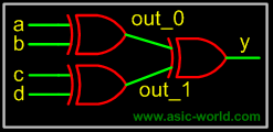
Instantiating a module 1 //-----------------------------------------------------
2 // This is simple parity Program
3 // Design Name : parity
4 // File Name : parity.v
5 // Function : This program shows how a verilog
6 // primitive/module port connection are done
7 // Coder : Deepak
8 //-----------------------------------------------------
9 module parity (
10 a , // First input
11 b , // Second input
12 c , // Third Input
13 d , // Fourth Input
14 y // Parity output
15 );
16
17 // Input Declaration
18 input a ;
19 input b ;
20 input c ;
21 input d ;
22 // Ouput Declaration
23 output y ;
24 // port data types
25 wire a ;
26 wire b ;
27 wire c ;
28 wire d ;
29 wire y ;
30 // Internal variables
31 wire out_0 ;
32 wire out_1 ;
33
34 // Code starts Here
35 xor u0 (out_0,a,b);
36
37 xor u1 (out_1,c,d);
38
39 xor u2 (y,out_0,out_1);
40
41 endmodule // End Of Module parity
Question : What is the difference between u0 in module adder and u0 in module parity?
Bạn Có Đam Mê Với Vi Mạch hay Nhúng - Bạn Muốn Trau Dồi Thêm Kĩ Năng
Mong Muốn Có Thêm Cơ Hội Trong Công Việc
Và Trở Thành Một Người Có Giá Trị Hơn
Bạn Chưa Biết Phương Thức Nào Nhanh Chóng Để Đạt Được Chúng
Hãy Để Chúng Tôi Hỗ Trợ Cho Bạn. SEMICON