


I²C (Inter-Integrated Circuit) is a multi-master serial single-ended computer bus invented by Philips that is used to attach low-speed peripherals to a motherboard, embedded system, or cellphone. Since the mid 1990s several competitors (e.g. Siemens AG (later Infineon Technologies AG), NEC, Texas Instruments, STMicroelectronics (formerly SGS-Thomson), Motorola (later Freescale), Intersil, etc.)
brought I²C products on the market, which are fully compatible to the NXP (formerly Philips' semiconductor division) I²C-system. As of October 1, 2006, no licensing fees are required to implement the I²C protocol. However, fees are still required in order to have I²C slave addresses allocated by NXP.[1]
SMBus is a subset of I²C that defines stricter electrical and protocol conventions. One purpose of SMBus is to promote robustness and interoperability. Accordingly, modern I²C systems incorporate policies and rules from SMBus, and the line between these two standards is often blurred in practice.
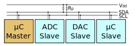
I²C uses only two bidirectional open-drain lines, Serial Data Line(SDA) and Serial Clock (SCL), pulled up with resistors. Typical voltages used are +5 V or +3.3 V although systems with other voltages are permitted.
The I²C reference design has a 7-bit address space with 16 reserved addresses, so a maximum of 112 nodes can communicate on the same bus. Common I²C bus speeds are the 100 kbit/s standard mode and the 10 kbit/s low-speed mode, but arbitrarily low clock frequencies are also allowed. Recent revisions of I²C can host more nodes and run faster (400 kbit/s Fast mode, 1 Mbit/s Fast mode plus or Fm+, and 3.4 Mbit/s High Speed mode); those speeds are more widely used on embedded systems than on PCs. There are other features, such as 10-bit addressing.
Note that the bit rates quoted are for the transactions between master and slave without clock stretching or other hardware overhead. Protocol overheads include a slave address and perhaps a register address within the slave device as well as per-byte ACK/NACK bits. So the actual transfer rate of user data is lower than those peak bit rates alone would imply. For example, if each interaction with a slave inefficiently allows only 1 byte of data to be transferred, the data rate will be less than half the peak bit rate.
The maximum number of nodes is limited by the address space, and also by the total bus capacitance of 400 pF, which restricts practical communication distances to a few meters.
Message protocols
I²C defines three basic types of message, each of which begins with a START and ends with a STOP:
- Single message where a master writes data to a slave;
- Single message where a master reads data from a slave;
- Combined messages, where a master issues at least two reads and/or writes to one or more slaves.
In a combined message, each read or write begins with a START and the slave address. After the first START, these are also called repeated START bits; repeated START bits are not preceded by STOP bits, which is how slaves know the next transfer is part of the same message.
Any given slave will only respond to particular messages, as defined by its product documentation.
Pure I²C systems support arbitrary message structures. SMBus is restricted to nine of those structures, such as read word N and write word N, involving a single slave. PMBusGroup protocol, allowing multiple such SMBus transactions to be sent in one combined message. The terminating STOP indicates when those grouped actions should take effect. For example, one PMBus operation might reconfigure three power supplies (using three different I2C slave addresses), and their new configurations would take effect at the same time: when they receive that STOP. extends SMBus with a
With only a few exceptions, neither I²C nor SMBus define message semantics, such as the meaning of data bytes in messages. Message semantics are otherwise product-specific. Those exceptions include messages addressed to the I²C general call address (0x00) or to the SMBus Alert Response Address; and messages involved in the SMBus Address Resolution Protocol (ARP) for dynamic address allocation and management.
In practice, most slaves adopt request/response control models, where one or more bytes following a write command are treated as a command or address. Those bytes determine how subsequent written bytes are treated and/or how the slave responds on subsequent reads. Most SMBus operations involve single byte commands.
Physical layer
At the physical layer, both SCL & SDA lines are of open-drain design, thus, pull-up resistors are needed. Pulling the line to ground is considered a logical zero while letting the line float is a logical one. This is used as a channel access method. High speed systems (and some others) also add a current source pull up, at least on SCL; this supports faster rise times and higher bus capacitance. Transitions for data bits are always performed while the clock is low, transitions while it is high indicate start and stop bits.
When one node is transmitting a logical one (i.e., letting the line float to Vdd) and another transmits a logical zero then the first node can sense this because the line is not in a logical one state — it is not pulled up to Vdd. When used on SCL, this is called "clock stretching" and gives slaves a flow control mechanism. When used on SDA, this is called arbitration and ensures there is only one transmitter at a time.
Clock stretching uses SCL
One of the more significant features of the I²C protocol is clock stretching. An addressed slave device may hold the clock line (SCL) low after receiving (or sending) a byte, indicating that it is not yet ready to process more data. The master that is communicating with the slave will attempt to raise the clock to transfer the next bit, but must verify that the clock line was actually raised. If the slave is clock stretching, the clock line will still be low (because the connections are open-drain). The same is true if a second, slower, master tries to drive the clock at the same time. (If there is more than one master, all but one of them will normally lose arbitration.)
Clock stretching is not used by masters in single-master configurations. When a master wants to slow the rate of data transfer, it just delays issuing the next clock edge. Some masters, such as those found inside custom ASICs may not support clock stretching; often these devices will be labeled as a "two-wire interface" and not I²C.
To improve its robustness, SMBus places limits on how far clocks may be stretched. Hosts and slaves adhering to those limits can't block access to the bus for more than a short time, which is not a guarantee made by pure I²C systems.
Arbitration uses SDA
Every master monitors the bus for start and stop bits, and does not start a message while another master is keeping the bus busy. However, two masters may start transmission at about the same time; in this case, arbitration occurs. Slave transmit mode can also be arbitrated, when a master addresses multiple slaves, but this is less common. In contrast to protocols (such as Ethernet) that use random back-off delays before issuing a retry, I²C has a deterministic arbitration policy. Each transmitter checks the level of the data line (SDA) and compares them with the levels it expects; if they don't match, that transmitter has lost arbitration, and drops out of this protocol interaction.
For example, if one transmitter sets SDA to 1 (not driving a signal) and a second transmitter sets it to 0 (pull to ground), the result is that the line is low. The first transmitter then observes that the level of the line is different than expected, and concludes that another node is transmitting. The first node to notice such a difference is the one that loses arbitration: it stops driving SDA. If it's a master, it also stops driving SCL and waits for a STOP; then it may try to reissue its entire message. In the meantime, the other node has not noticed any difference between the expected and actual levels on SDA, and therefore continues transmission. It can do so without problems because so far the signal has been exactly as it expected; no other transmitter has disturbed its message.
If the two masters are sending a message to two different slaves, the one sending the lower slave address always "wins" arbitration in the address stage. Since the two masters may send messages to the same slave address—and addresses sometimes refer to multiple slaves—arbitration must continue into the data stages.
Arbitration occurs very rarely, but is necessary for proper multi-master support. As with clock-stretching, not all devices support arbitration. Those that do generally label themselves as supporting "multi-master" communication.
SMBus uses arbitration in two additional contexts, both of which are used to pass information asynchronously from slaves to the (single) host. The first context is that hosts must support the "host notify protocol". That is a restricted multi-master mode in which slaves write messages to the reserved "SMBus Host" address (0x08), passing their address and two bytes of data. When two slaves try to notify the host at the same time, one of them will lose arbitration and need to retry. The other context is that pure slave devices which issue the SMBALERT# interrupt need to arbitrate when they reply to requests issued to the reserved "SMBus Alert Response Address" (0x0c), which is a kind of broadcast address. When they successfully reply with their own address, winning an arbitration in "slave transmit" mode, they stop raising that interrupt. In both cases, arbitration applies when the slave address is transmitted.
Data transfer is initiated with the START bit (S) when SDA is pulled low while SCL stays high. Then, SDA sets the transferred bit while SCL is low (blue) and the data is sampled (received) when SCL rises (green). When the transfer is complete, a STOP bit (P) is sent by releasing the data line to allow it to be pulled up while SCL is constantly high.
Example of bit-banging the I2C Master protocol
unsigned start = 0;
unsigned read_bit(void)
{
	unsigned bit;

	/* Let the slave drive data */
	READSDA();
	I2CDELAY(I2CSPEED/2);
	/* Clock stretching */
	while (READSCL() == 0);
	/* SCL is high, now data is valid */
	bit = READSDA();
	I2CDELAY(I2CSPEED/2);
	CLRSCL();
	return bit;
}

void write_bit(unsigned bit)
{
	if (bit) {
		READSDA();
	} else {
		CLRSDA();
	}
	I2CDELAY(I2CSPEED/2);
	/* Clock stretching */
	while (READSCL() == 0);
	/* SCL is high, now data is valid */
	/* If SDA is high, check that nobody else is driving SDA */
	if (bit) {
                if (READSDA() == 0) {
		        ARBITRATION_LOST();
		}
	}
	I2CDELAY(I2CSPEED/2);
	CLRSCL();
}

void start_cond(void)
{
	if (start) {
		/* set SDA to 1 */
		READSDA();
		I2CDELAY(I2CSPEED/2);
		/* Clock stretching */
		while (READSCL() == 0);
	}
	if (READSDA() == 0) {
		ARBITRATION_LOST();
	}
	/* SCL is high, set SDA from 1 to 0 */
	CLRSDA();
	I2CDELAY(I2CSPEED/2);
	CLRSCL();
	start = 1;
}

void stop_cond(void)
{
	/* set SDA to 0 */
	CLRSDA();
	I2CDELAY(I2CSPEED/2);
	/* Clock stretching */
	while (READSCL() == 0);
	/* SCL is high, set SDA from 0 to 1 */
	if (READSDA() == 0) {
		ARBITRATION_LOST();
	}
	I2CDELAY(I2CSPEED/2);
	start = 0;
}

unsigned tx(int send_start, int send_stop, unsigned char byte)
{
	unsigned bit;
	unsigned nack;

	if (send_start) {
		start_cond();
	}
	for (bit = 0; bit < 8; bit++) {
		write_bit(byte & 0x80);
		byte <<= 1;
	}
	nack = read_bit();
	if (send_stop) {
		stop_cond();
	}
	return nack;
}

unsigned char rx (int nak, int send_stop)
{
	unsigned char byte = 0;
	unsigned bit;

	for (bit = 0; bit < 8; bit++) {
             byte <<= 1;
             byte |= read_bit();
	}
	write_bit(nak);
	if (send_stop) {
		stop_cond();
	}
	return byte;
}
Applications
I²C is appropriate for peripherals where simplicity and low manufacturing cost are more important than speed. Common applications of the I²C bus are:
- Reading configuration data from SPD EEPROMs on SDRAM, DDR SDRAM, DDR2 SDRAM memory sticks (DIMM) and other stacked PC boards
- Supporting systems management for PCI cards, through an SMBus 2.0 connection.
- Accessing NVRAM chips that keep user settings.
- Accessing low speed DACs and ADCs.
- Changing contrast, hue, and color balance settings in monitors (Display Data Channel).
- Changing sound volume in intelligent speakers.
- Controlling OLED/LCD displays, like in a cellphone.
- Reading hardware monitors and diagnostic sensors, like a CPU thermostat and fan speed.
- Reading real time clocks.
- Turning on and turning off the power supply of system components.
A particular strength of I²C is that a microcontroller can control a network of device chips with just two general-purpose I/O pins and software.
Peripherals can also be added to or removed from the I²C bus while the system is running, which makes it ideal for applications that require hot swapping of components.
Buses like I²C became popular when computer engineers realized that much of the manufacturing cost of an integrated circuit design results from its package size and pin count. A smaller package also usually weighs less and consumes less power[citation needed], which is especially important in cellphones and portable computing. Those concerns multiply at the board level, where routing lots of signals in parallel takes up scarce space.
(Theo en.wikipedia.org)