| | To facilitate the conversion to NAND and NOR logic, we have two new graphic symbols for these gates. |
| | 
|
| | NAND Gate |
| | 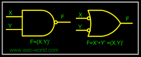 |
| |
|
| | NOR Gate |
| | 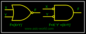 |
| |
|
 | Realization of logic function using NAND gates |
| | Any logic function can be implemented using NAND gates. To achieve this, first the logic function has to be written in Sum of Product (SOP) form. Once logic function is converted to SOP, then is very easy to implement using NAND gate. In other words any logic circuit with AND gates in first level and OR gates in second level can be converted into a NAND-NAND gate circuit. |
| |
|
| | Consider the following SOP expression |
| |
|
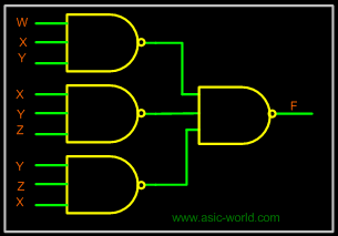
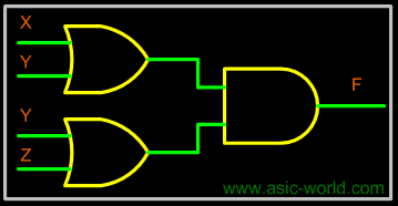
| | F = W.X.Y + X.Y.Z + Y.Z.W |
| |
|
| | The above expression can be implemented with three AND gates in first stage and one OR gate in second stage as shown in figure. |
| |
|
| | 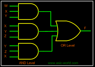 |
| |
|
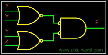
| | If bubbles are introduced at AND gates output and OR gates inputs (the same for NOR gates), the above circuit becomes as shown in figure. |
| |
|
| | 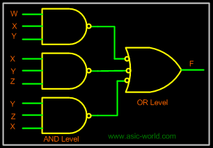 |
| |
|
| | Now replace OR gate with input bubble with the NAND gate. Now we have circuit which is fully implemented with just NAND gates. |
| |
|
| |  |
| |
|
| | Realization of logic gates using NAND gates |
| |
|
| |
|
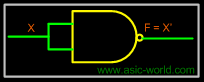
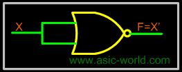
 | Implementing an inverter using NAND gate |
| |
|
| | | Input | Output | Rule | | (X.X)' | = X' | Idempotent | |
| |
|
| |  |
| |
|
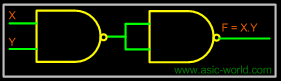
| | Implementing AND using NAND gates |
| |
|
| | | Input | Output | Rule | | ((XY)'(XY)')' | = ((XY)')' | Idempotent | |
| = (XY) | Involution | |
| |
|
| |  |
| |
|
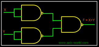
| | Implementing OR using NAND gates |
| |
|
| | | Input | Output | Rule | | ((XX)'(YY)')' | = (X'Y')' | Idempotent | |
| = X''+Y'' | DeMorgan | |
| = X+Y | Involution | |
| |
|
| |  |
| |
|
| |
|
| | Implementing NOR using NAND gates |
| |
|
| | | Input | Output | Rule | | ((XX)'(YY)')' | =(X'Y')' | Idempotent | |
| =X''+Y'' | DeMorgan | |
| =X+Y | Involution | |
| =(X+Y)' | Idempotent | |
| |
|
| | |
| |
|
| | Realization of logic function using NOR gates |
| | Any logic function can be implemented using NOR gates. To achieve this, first the logic function has to be written in Product of Sum (POS) form. Once it is converted to POS, then it's very easy to implement using NOR gate. In other words any logic circuit with OR gates in first level and AND gates in second level can be converted into a NOR-NOR gate circuit. |
| |
|
| | Consider the following POS expression |
| |
|
| | F = (X+Y) . (Y+Z) |
| |
|
| | The above expression can be implemented with three OR gates in first stage and one AND gate in second stage as shown in figure. |
| |
|
| |  |
| |
|
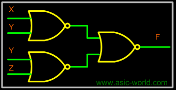
| | If bubble are introduced at the output of the OR gates and the inputs of AND gate, the above circuit becomes as shown in figure. |
| |
|
| |  |
| |
|
| | Now replace AND gate with input bubble with the NOR gate. Now we have circuit which is fully implemented with just NOR gates. |
| |
|
| |  |
| |
|
| | Realization of logic gates using NOR gates |
| |
|
| |
|
| | Implementing an inverter using NOR gate |
| |
|
| | | Input | Output | Rule | | (X+X)' | = X' | Idempotent | |
| |
|
| |  |
| |
|
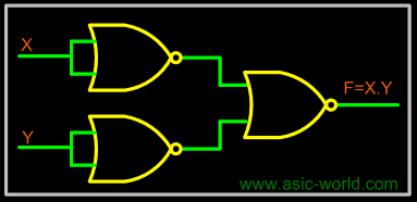
| | Implementing AND using NOR gates |
| |
|
| | | Input | Output | Rule | | ((X+X)'+(Y+Y)')' | =(X'+Y')' | Idempotent | |
| = X''.Y'' | DeMorgan | |
| = (X.Y) | Involution | |
| |
|
| |  |
| |
|
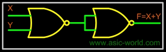
| | Implementing OR using NOR gates |
| |
|
| | | Input | Output | Rule | | ((X+Y)'+(X+Y)')' | = ((X+Y)')' | Idempotent | |
| = X+Y | Involution | |
| |
|
| |  |
| |
|
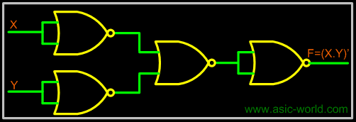
| | Implementing NAND using NOR gates |
| |
|
| | | Input | Output | Rule | | ((X+Y)'+(X+Y)')' | = ((X+Y)')' | Idempotent | |
| = X+Y | Involution | |
| = (X+Y)' | Idempotent | |
| |
|
| |  |