
Logic Circuit Modeling
From what we have learnt in digital design, we know that there could be only two types of digital circuits. One is combinational circuits and the second is sequential circuits. There are very few rules that need to be followed to get good synthesis output and avoid surprises.
Combinational Circuit Modeling using assign
assign y = (a&b) | (c^d);
Tri-state buffer

1 module tri_buf (a,b,enable);
2 input a;
3 output b;
4 input enable;
5 wire a,enable;
6 wire b;
7
8 assign b = (enable) ? a : 1'bz;
9
10 endmodule
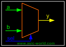
Mux

Multiply by 2
1 module muliply (a,product);
2 input [3:0] a;
3 output [4:0] product;
4 wire [4:0] product;
5
6 assign product = a << 1;
7
8 endmodule
3 is to 8 decoder
1 module decoder (in,out);
2 input [2:0] in;
3 output [7:0] out;
4 wire [7:0] out;
5 assign out = (in == 3'b000 ) ? 8'b0000_0001 :
6 (in == 3'b001 ) ? 8'b0000_0010 :
7 (in == 3'b010 ) ? 8'b0000_0100 :
8 (in == 3'b011 ) ? 8'b0000_1000 :
9 (in == 3'b100 ) ? 8'b0001_0000 :
10 (in == 3'b101 ) ? 8'b0010_0000 :
11 (in == 3'b110 ) ? 8'b0100_0000 :
12 (in == 3'b111 ) ? 8'b1000_0000 : 8'h00;
13
14 endmodule
Combinational Circuit Modeling using always
While modeling using always statements, there is the chance of getting a latch after synthesis if care is not taken. (No one seems to like latches in design, though they are faster, and take lesser transistor. This is due to the fact that timing analysis tools always have problems with latches; glitch at enable pin of latch is another problem)
One simple way to eliminate the latch with always statement is to always drive 0 to the LHS variable in the beginning of always code as shown in the code below.
3 is to 8 decoder using always
1 module decoder_always (in,out);
2 input [2:0] in;
3 output [7:0] out;
4 reg [7:0] out;
5
6 always @ (in)
7 begin
8 out = 0;
9 case (in)
10 3'b001 : out = 8'b0000_0001;
11 3'b010 : out = 8'b0000_0010;
12 3'b011 : out = 8'b0000_0100;
13 3'b100 : out = 8'b0000_1000;
14 3'b101 : out = 8'b0001_0000;
15 3'b110 : out = 8'b0100_0000;
16 3'b111 : out = 8'b1000_0000;
17 endcase
18 end
19
20 endmodule
Sequential Circuit Modeling
Use meaningful names for signals and variables
Don't mix level and edge sensitive elements in the same always block
Avoid mixing positive and negative edge-triggered flip-flops
Use parentheses to optimize logic structure
Use continuous assign statements for simple combo logic
Use nonblocking for sequential and blocking for combo logic
Don't mix blocking and nonblocking assignments in the same always block (even if Design compiler supports them!!).
Be careful with multiple assignments to the same variable
Define if-else or case statements explicitly
Bạn Có Đam Mê Với Vi Mạch hay Nhúng - Bạn Muốn Trau Dồi Thêm Kĩ Năng
Mong Muốn Có Thêm Cơ Hội Trong Công Việc
Và Trở Thành Một Người Có Giá Trị Hơn
Bạn Chưa Biết Phương Thức Nào Nhanh Chóng Để Đạt Được Chúng
Hãy Để Chúng Tôi Hỗ Trợ Cho Bạn. SEMICON
